The focus of this paper is: how to correctly select the rounding pressure angle of the rib cutter when the gear end face is chamfered. At this time, if the tool end pressure angle is still equal to the gear end pressure angle, the chamfer on the sharp side of the tooth portion will be uneven, resulting in a small chamfered chamfer and a large chamfered root, as shown by the middle curve D. At this time, if you want to obtain a uniform chamfering curve on the sharp side of the workpiece, the circular pressure angle of the tool should be equal to the circular pressure angle of the curve C projected on the plane A. It can be seen that the pressure angle after projection has increased significantly.
2.2 The design of the pressure angle of the end face of the extruded rib cutter is calculated as the correct circular pressure angle of the rib cutter after the chamfering of the tooth end. It is necessary to calculate the rounding pressure angle fs of the curve C projected on the plane A. The following formula is used to derive its calculation formula: as shown, it is known that the workpiece end face modulus ms; the circle diameter df; the arc tooth thickness sfs; the workpiece outer diameter de; the workpiece tooth number z; the circle round spiral angle f; End face pressure angle fs; other parameters are as shown.
According to the geometric relationship, (1) the base circle end face arc tooth thickness Sbs: Sbs = db (Sfs / df invfs) (2) the base circular tooth groove width Wbs and the cogging half angle b: Wbs = db / z - Sbs; b =Wbs/db(3)=0, the X-axis coordinate of the circle xf:xf=05dfsin(b fs)(1) where: fs=tgfs-fs=invfs When =0, the Cartesian coordinate xe on the top circle :xe=05desin(b es)(2) where: es=tges-es=inves(es is the top pressure angle of the workpiece) (4) When >0, a space curve C is formed on the sharp side tooth surface of the workpiece After projecting the curve C to the plane A, a new curve is formed. The pressure angle of the new curve increases, and the coordinates of the circle and the top circle also change, forming new coordinates.
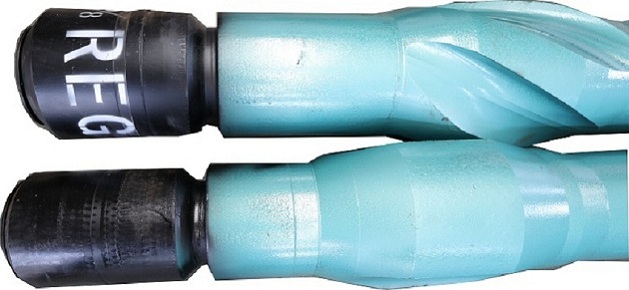
By-pass assembly has two positions; by-pass and close. It is in by-pass position during trip operation, and circulates mud fluid in the drill string into the annular space by-passing the idle motor, so that no mud may spray out onto the platform during the trip operation. When mud flow rate and pressure reach the setting value, the valve stem moves down and closes the valve. Meanwhile, mud stream flows through the motor, and converts the pressure energy into mechanical energy. As mud flow rate is too low, or mud pump stops, and as the pressure produced is not enough to overcome the spring force and the static friction force, the spring presses the stem upward, and by-pass is in open position. In general, the cross-over subs are used in deep well, large angle well, horizontal well or when hollow rotor is selected.

By-Pass Assembly And Parts,By-Pass Valve Assembly,Automatic Bypass Valve,Pressure Bypass Valve
Weifang Shengde Petroleum Machinery Manufacturing Co., Ltd. , http://www.sdpetromachine.com
![<?echo $_SERVER['SERVER_NAME'];?>](/template/twentyseventeen/skin/images/header.jpg)