PEM fuel cell cathode catalyst layer characteristics
Gao Xiaojia   Sun Hong   Zhang Wei
(School of Transportation and Mechanical Engineering, Shenyang Jianzhu University, Shenyang 110168 , China )
Abstract: In order to improve the characteristics of the catalyst layer and the performance of PEM fuel cells, accelerate its promotion and application. A mathematical model of cathode heat and mass transfer in a PEM fuel cell is presented . The law of oxygen volume fraction, current density, impedance and temperature distribution in the cathode catalyst layer is simulated. It is found that under the simulated conditions, in the mass transfer in the cathode catalyst layer, the proton transfer process is the control process of the cathode performance; along the gas channel direction, the oxygen concentration, current density, impedance and temperature in the catalyst layer are gradually reduced; Along the Y- axis, the oxygen volume fraction, impedance and temperature gradually decrease, and the current density increases. The research results have an important reference for the optimization and improvement of the cathode structure of PEM fuel cells.
Key words: proton exchange membrane; fuel cell; mathematical model; heat and mass transfer
CLC number: TQ 031 Â Â Â Â Â Â Document identification code: A
0 Introduction
PEM (Proton Exchange Membrane, referred to as PEM) fuel cell is a clean, efficient power generation system, with a very wide range of applications, many internationally renowned scholars have invested a lot of time studying it [1]. For example, You et al. [2] , Wang et al. [3] and Sun et al. [4] respectively established a heat and mass transfer two-phase flow model in PEMFC , and simulated the internal two-phase mass transfer law and its influencing factors. Sun et al. [5] , Liu et al. [6] and Mench et al. [7] used the measurement spot method, sub-cell method and smooth segmentation method to study the current density distribution inside PEMFC and analyzed its internal The law of current density distribution and its influencing factors. Wang et al. [8-9] tested and simulated the performance characteristics of serpentine flow field and interdigitated PEMFC . Despite the many valuable results achieved in the above literature, to date, there has been little literature on the performance of PEMFC cathode catalyst layers.
Paper presents a mathematical model to study the volume of oxygen PEM fuel cell cathode catalyst layer distribution of scores, current density distribution, impedance distribution and temperature distribution is optimized to provide useful assistance PEM fuel cell cathode.
1 geometry and mathematical model
The humidified air enters the cathode of the battery in the direction of the arrow, passes through the cathode diffusion layer and reaches the catalyst layer, where oxygen reacts with the protons and electrons from the anode to form water. The generated water and the moisture from the anode will diffuse to the cathode gas channel or return to the anode by back diffusion. Figure 1 is the area involved in the model calculation.

The basic assumptions needed to build a model:
( 1 ) The fluid flow throughout the battery is laminar;
( 2 ) The fuel cell system is in a stable state; Â
( 3 ) the porous medium of the gas diffusion layer, the catalyst layer and the proton exchange membrane is isotropic;
Continuous equation:

Where ε is the porosity. In the gas channel, if there is no liquid water, the porosity is 0 .
Momentum equation
The momentum equation for mixed gas and liquid water is
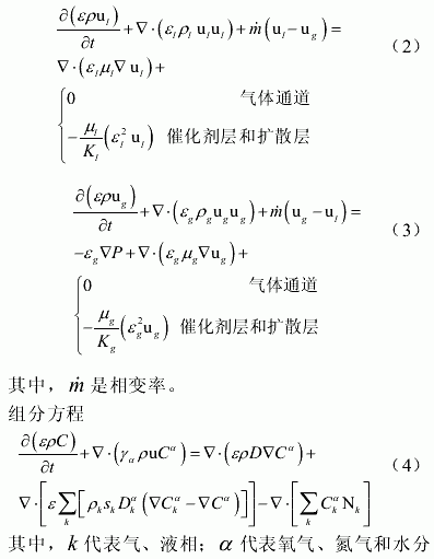
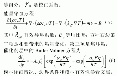
2 simulation results and discussion
The PEM fuel cell in the simulation is a monomer with an effective area of 5 cm2 , a DC field. The finite volume method is used to solve the boundary conditions of the governing equation and its model. Table 1 is the basic parameters of the PEM fuel cell involved in the model calculation .
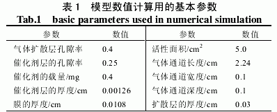
Figure 2 is a graph showing the distribution of oxygen in the cathode catalyst layer at a cathode and anode humidification temperature of 333 K and a current density of 1.08 A/cm2 . It can be seen that the volume fraction of oxygen decreases in the direction of air flow, mainly due to the consumption of oxygen in the cathode. In the longitudinal direction, the catalyst layer decreases from the gas diffusion layer interface to the proton exchange membrane interface. This shows that the concentration of oxygen in the cathode catalyst layer is not uniform, and the electrochemical reaction rate is also non-uniform.

Figure 3 is a graph showing the current density distribution in the cathode catalyst layer at a humidification temperature of 333 K and an average current density of 1.08 A/cm2 . It can be seen from the figure that the current density gradually decreases along the direction of the gas channel. The current density increases as the catalyst layer diffuses from near to near the proton exchange membrane. This is due to the fact that in this direction, the mass fraction of the proton is increased and the electrochemical reaction rate is increased. This also shows that when the battery temperature is 353 K and the humidification temperature is 333 K , the transfer of protons is the control process during the transfer of the cathode material.
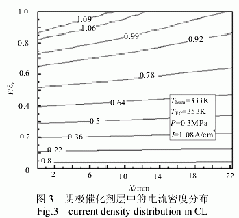
Figure 4 shows the impedance distribution in the cathode catalyst layer at a battery temperature of 353 K , a humidification temperature of 333 K , and a current density of 1.08 A/cm2 . It can be seen that the impedance decreases along the direction of the gas channel. Due to the accumulation of moisture generated by the electrochemical reaction in the direction of the gas passage, the moisture content is gradually increased, and the proton transfer resistance is lowered. The catalyst layer is reduced from the side of the diffusion layer to the side of the proton exchange membrane. The main reason is that near the proton exchange membrane side, the electrochemical reaction rate is high, and the generated water is large, and the proton exchange membrane component has a high water content and a low proton transfer resistance.
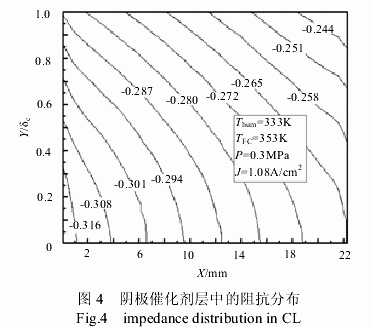
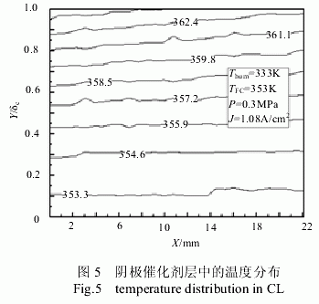
Fig. 5 is a temperature distribution in the cathode catalyst layer when the battery heating temperature was 353 K , the humidification temperature was 333 K , and the current density was 1.08 A/cm2 . It can be seen from the figure that the temperature is gradually decreasing in the direction of the gas channel. The main reason is that the oxygen volume fraction and the effective porosity decrease, resulting in a decrease in the electrochemical reaction rate. In the catalyst layer, from the side of the diffusion layer to the side of the proton exchange membrane, the temperature rises. The main reason is that near the proton exchange membrane side, the proton concentration is large, and the electrochemical reaction rate is high, resulting in a higher temperature.
3 Conclusion
( 1 ) Proton transfer is a control process for mass transfer in the cathode catalyst layer under simulated conditions;
( 2 ) along the gas channel direction, the oxygen concentration, temperature, impedance and current density in the cathode catalyst layer are gradually reduced;
( 3 ) From the side of the diffusion layer to the side of the proton exchange membrane, the oxygen volume fraction, temperature and impedance in the catalyst layer are lowered, and the current density is increased.
Shock Absorber Cover,Shock Absorber Dust Cover,Shock Dust Cover,Absorber Cover
Ningbo Metal Sharing Supply Chain Management Co., Ltd , https://www.customsharing.com
![<?echo $_SERVER['SERVER_NAME'];?>](/template/twentyseventeen/skin/images/header.jpg)