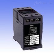
The frequency transmitter is a single-channel standard DC voltage or DC current that is isolated from the measured AC voltage frequency and converted into a linear proportional output . SCM technology, accurate latest algorithm to achieve accurate measurement of AC circuit frequency; is used for DC power supply cabinet supporting products.

The main series are: szxrdt frequency transmitter, szxrdt-my frequency sensor .
Uses: It is used to measure the AC frequency, isolate the linear DC signal of the transmission output, and send it to the remote device, computer, and automatic control system;
Measurement: single phase, three phase system
Input range: 50±5Hz, 50±1Hz, 50±0.5Hz, 0~60Hz accuracy: ±0.1%RO
Output: 0~20mAdc, 4~20mAdc, 0~10Vdc, 0~5Vdc, etc.
Working power: AC220V±10% or AC/DC24~265V
Dimensions: 112 (L) × 65 (W) × 70 (H) mm
Installation method: 35mm standard rail, base screw installation
Common specification examples
Model: LF-H2V1-A420-A2;
Class: ±0.2%
Input: 45~55Hz, 100Vac, 50Hz;
Output: 4~20mAdc
Aux.power: AC220V
Description: This model is a frequency transmitter, 45~55Hz power frequency signal input, output 4~20mAdc, working power AC220V
The frequency transmitter takes the single-chip microcomputer as the core and adopts the latest algorithm to realize the accurate measurement of the AC circuit frequency. It is used to measure the AC frequency, isolate the transmission output linear DC signal, and send it to remote devices, computers, automatic control systems, etc.
Measurement: single phase, three phase system
Input range: 50±5Hz, 50±1Hz, 50±0.5Hz, 0~60Hz
Output: 0~20mAdc, 4~20mAdc, 0~10Vdc, 0~5Vdc, etc.
Working power: AC220V±10% or AC/DC24~26
It is widely used in electrical equipment, automatic control and dispatching systems of electric power, post and telecommunications, petroleum, coal, metallurgy, railway, municipal and other departments.
â—†Input and output
Input current: AC0~500V, frequency 0~10Hz optional
â—† absorbed power
≤0.22VA/220V
≤0.10VA/100V
â—†Overload capability
2 times continuous
â—†Output signal:
DC0~5V, 1~5V, 0~20mA, 4~20mA, etc.
â—†Load resistance
Current output: RL≤270Ω for +12V and +15V auxiliary power supply
RL≤600Ω when +24V auxiliary power supply
Voltage output: RL≥2kΩ
â—†Performance indicators
Implementation standards: GB/T 13850-1998, IEC688: 1992
Accuracy: 0.2%, 0.5%
Machine power consumption: ≤1VA
Power frequency withstand voltage: input / output / housing: AC2kV / min.1mA
Insulation resistance: ≥20MΩ (DC500V)
Impact voltage: 5KV (peak), 1.2/50us
Response time: ≤300ms
Storage conditions: -40 to 70 ° C, 20 to 95% (no condensation)
Working environment: -10 ~ 50 ° C, 20 ~ 90% (no condensation)
Installation method: DIN (35mm) rail mounting and M4 screw fixing
1. Installation of the transmitter
The transmitter is mounted on a standard DIN35 rail card for ease of use.
1 hook the lower side of the transmitter fixing card slot on the mounting rail;
2 Push the transmitter up and rotate to press the upper side of the transmitter to the rail, then the transmitter is mounted on the rail;
3 When removing from the track, push up and rotate the upper side of the transmitter as shown in the figure to remove the transmitter;
2. When the transmitter is shipped from the factory, it has been accurately set according to the “Product Standardsâ€, and the user can be energized after the connection is correct. When the power is turned on, the red RUN operation indicator should flash. The transmitter has no special requirements for the auxiliary power supply, and multiple transmitters can share a set of power supplies. If you purchase a commercially available regulated power supply, the isolation voltage of the power supply is required to be ≥2000VAC, and the DC output ripple is <10mV.
3. Please connect the input and output signals in strict accordance with the transmitter terminal definition diagram. Otherwise, the transmitter may be damaged or the output value may be wrong.
4. For the accuracy of the transmitter to be tested, it should be carried out under the following conditions:
a) Standard signal source with accuracy of 0.05 or higher and measuring instrument with 0.05 or higher;
b) Auxiliary power supply: nominal value ± 0.5%, ripple ≤ 5mV; ambient temperature: 25 ° C ± 5 ° C; relative humidity: RH (45 ~ 75)%;
Reference editing area
Smc Zse30A,Smc Digital Pressure Switch,Zse20 Smc,Festo Digital Pressure Switch
SHINYEE TECHNOLOGY (NINGBO) CO., LTD , https://www.pneuvalve.com
![<?echo $_SERVER['SERVER_NAME'];?>](/template/twentyseventeen/skin/images/header.jpg)