About the wiring specifications of the equipment room? What is the internal network core equipment and so on, let's take a look at it today.
First, the common machine room noun explanation
Let's first understand some common terms and explanations in the computer room. Although we often encounter it, we rarely know what it means.
Computer room network topology:
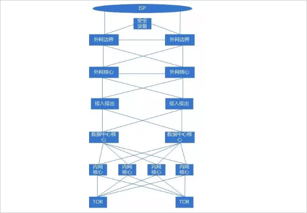
TOR switch: internal network access switch, 1U box network equipment, equipped with 48 10G optical ports and four 40G optical ports; 10G optical port with AOC cable to connect servers 10 Gigabit ports, 40G optical ports with MPO fiber uplinks To the core of the intranet of the equipment room, a single TOR covers the servers of two cabinets;
ILO: Server ILO access switch, also known as management network access switch, 1U box network equipment, equipped with 48 10/100/1000M adaptive electrical ports and 1 1/10G optical port, 48 electrical ports connected to the server Gigabit Ethernet port and network device MGMT port; optical port is connected to the core of the computer room management network with 10G multimode fiber, and a single ILO covers two cabinets of servers and network devices;
Core of the internal network: network core equipment, frame network equipment, equipped with multiple 40G optical ports and 10G optical ports, etc. (depending on the configuration), the 40G optical port is connected to the TOR in the equipment room through the MPO fiber, and the 40G optical port passes through the MPO fiber. Linked to the core equipment of the computer room data center;
Data center core: network core equipment, frame network equipment, equipped with multiple 40G optical ports and 10G optical ports (specifically, configuration), 40G optical ports are connected to the internal network core through MOP fiber, and 10G optical ports pass 10G single mode. Optical fiber connection transmission (dedicated line), 10G optical port is connected to the access device through 10G multimode optical fiber connection;
Unified access device: similar to a NAT translation device, used to convert between public and private network addresses. A single device is equipped with multiple 10G optical ports. The 10G optical port is connected to the data center core through multimode fiber. Core; additionally connected to the session synchronization switch through 10G multimode fiber for session synchronization between different devices;
External network core: The core network equipment in the external network area is equipped with 40G and 10G optical ports. The 10G optical port is connected to the unified access and access, the external network access of the independent external network area, and the security device through the multimode optical fiber. The 40G optical port passes. MPO fiber uplink network boundary;
External network boundary: Network equipment connected to the ISP, with 40G and 10G optical ports. The 10G optical port is connected to the ISP device through the single-mode fiber. The other 10G optical port is connected to the security device through the multimode fiber. The 40G optical port is connected through the MPO fiber. External network core;
10G-AOC cable: Similar to the fiber of the optical fiber, the optical module is integrated at both ends to connect the TOR switch to the 10GE network port of the server.
Management network cable: Category 6 or Category 6 copper cable, RJ45 connector, used for connection between ILO access switch and server Gigabit Ethernet port and network device MGMT port;
Second, the wiring rules in the equipment room
The same IDC, the same specification rack, the wiring method should be consistent, which is convenient for daily operation and maintenance. Network equipment such as core network equipment, internal network access equipment, and management network access equipment should be neatly wired. The optical fiber and network cable should not block the air inlet and outlet of the network equipment. It should not be reserved to the bottom of the rack. The fiber and network cable are too long. The label on the sticker should be clear. The method of inserting the optical fiber and the network cable on the front of the network device should be as consistent as possible. The optical fiber and the network cable are tied together. The power cable and the network cable on the back of the network device are neat and uncluttered. The strong and weak cables are separated and have a sense of overallity.
1. Core equipment wiring specification
IDC core network equipment, especially the core equipment of the internal network, will have more interconnections than TOR, so there will be more optical fibers. The core network equipment fiber placement must be neat and tidy, and it should not be interspersed horizontally and vertically. The beautiful wiring inside the cabinet is one of the key points in the wiring specification of network equipment.
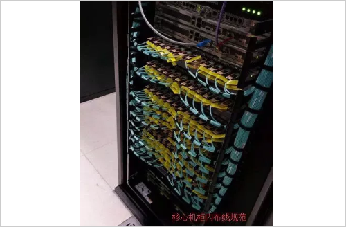
The fiber is laid vertically from the left or right side of the device, and the place where it is placed cannot block the air inlet and outlet of the network device. The optical fiber is bundled with a Velcro strap at intervals (note: the strap cannot be fixed with white), but the bundle cannot be too tight and the curvature is not too large, usually between 100 and 130 degrees, usually about 110 degrees (the same below) ), you should be able to release it freely, stick the label, and insert it into the device port, try not to block the label, and leave a certain length of space to facilitate the insertion and removal of the fiber.
2, internal network access wiring specification
The internal network access switch is located at the top of the rack. The MPO fiber of the internal network TOR switch 40G is connected to the inner network core, and the 10G-AOC cable is connected to the server. The 1G or 10G port of the ILO switch is connected to the core of the management network. The Gigabit port is connected to the server. The two cabinets in the equipment room share one internal network TOR and one ILO access switch. The 5 meter cable is used in the cabinet. Eight-8 cables are used in the adjacent cabinets, and approximately 18 servers are placed in each cabinet. Schematic diagram of fiber and network cable deployment:
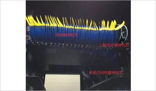
The cables placed on the internal network access switch are organized by the cable management device. Each of the four network cables on the cable management device is bundled with a cable tie. Each network cable is marked with a unique label and the other end is placed in the rack. Pallet position. The length of the fiber drop does not need to be too long, and the bending degree should not be too large. The fibers that are labeled and connected to different cores should be distinguished by labels of different colors.
3, the wiring inside the bridge specification
The interconnection cables between the network devices in the equipment room need to be routed through the bridge (except in the single cabinet).
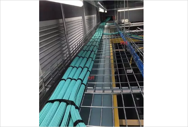
As shown in the figure, the optical fiber and the network cable in the bridge are placed separately and neatly, and are bundled with the cable tie at intervals to maintain the appearance.
4, the wiring specification within the cabinet
Inside the cabinet (ordinary server cabinets), there are mainly internal network AOC cables and ILO management network cable, and power cables. Therefore, the number of cables in a single cabinet is large. Each cable needs to be laid on the inside of the cabinet. As shown below
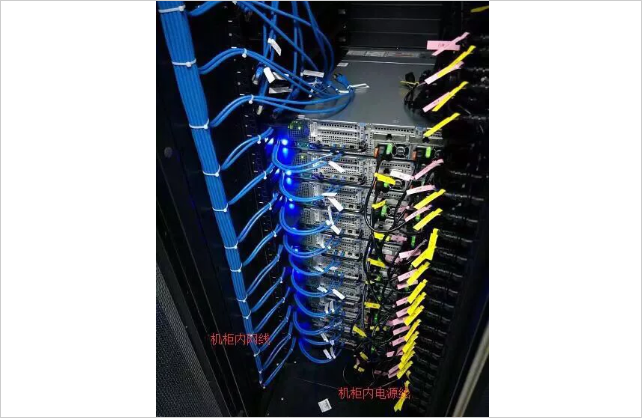
Different cables are distinguished by different color lines, such as internal network cable: blue, ILO cable: gray, power cable: black, and the reserved cable length should not be too long. It can be from one side PDU to the other side PDU. Setting a long cable will affect the cable. The wiring and bundling requirements between the upper and lower servers are as follows: (Because the network cable has electromagnetic interference, to be strong and weak, the power cable and the network cable should be bundled separately)

5, cable label specification
Core-intranet TOR tag: Since a single TOR has 4 MPO lines connected to 4 intranet cores respectively, the label color is used to distinguish the uplinks to different intranet cores, such as red, yellow, blue, and green. The internal network core 1, 2, 3, 4; the label format is unified with the "cabinet A ~ cabinet B # number of roots" mode, such as XX machine room -02-01 ~ XX machine room-01-08 #1. According to the custom, cabinet A is the core cabinet and cabinet B is the non-core cabinet.
Special equipment interconnection label: Whether it is interconnection wiring between special network equipment such as network cable or fiber optic fiber, the label is uniformly marked as "rack A~rack B# number one" mode, such as XX machine room -02-08~XX engine room-01 -08#1.
Internal network access switch-server interconnection label: The front panel reflects the rack position and port information of the internal network access switch, and the reverse side reflects the rack position information of the server; for example, the front A1-4-J-17-24-Gi1/1, Reverse J-17-01 (where A1-4 indicates the name of the machine room, J refers to the Jth column, 017 refers to 17 cabinets, 24 indicates the 24th pallet position, and Gi1/1 refers to 1/1 of the switch) Port. The reverse side is represented as the rack location of the server);
note:
1. 48U height in a single cabinet, one server per 2U space, that is, one tray per 2U, the correspondence from bottom to top is 01, 02, 03...24, etc.
2. Since there are two PDUs in a single cabinet, the two PDUs are named A and B. The power labels are named after letters and numbers. The numbers are in the front and the numbers are in two digits. . For example, 01A-24A, 01B-24B.
PVC Edge Banding
The main function of the edge banding is to seal the cross-section of the board, so as to avoid the damage of the board and the adverse factors (mainly moisture) in the process of use and prevent the formaldehyde inside the board from volatilizing, and at the same time achieve the effect of beautiful decoration.
The product has the following main features: smooth surface, no blistering, no ribbing, moderate gloss, smooth surface and back surface, uniform thickness, uniform width, reasonable hardness, high elasticity, good quality, strong wear resistance, trimmed and sealed The color of the side and the side is close to the surface color, not whitish, good gloss, and the overall color of the finished furniture is coordinated.
PVC furniture edge banding is relatively light, which is relative to metal and plexiglass. The reason for the lightness is not because it is a polymer compound, but because they are organic compounds, which are composed of carbon, hydrogen, oxygen, and chlorine. And other lighter elements.
The material of pvc furniture edge banding is plastic, which is easy to process. Plastic has plasticity, that is, it deforms after heating or pressurizing, and maintains its original shape after the temperature drops or the pressure disappears. It can be processed into edge bands of their respective shapes by extrusion and other methods, such as T-shaped edge bands, H-shaped edge bands, D-shaped edge bands, V-shaped edge bands, I-shapes, and so on.
pvc furniture edge banding is of high quality and low price, and the price of plastic is far less than that of metal.
PVC Edge Banding,Edge Banding Pvc,Pvc U Trim Edge Banding,Pvc Edge Banding Trimmer
Henan Shunbang Chemical Industry CO.,Ltd , https://www.sbpolymer.com


![<?echo $_SERVER['SERVER_NAME'];?>](/template/twentyseventeen/skin/images/header.jpg)